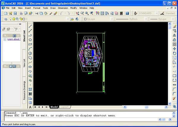
- DXF(Drawing Exchange Format) is a CAD file developed by Autodesk.
- It is for enabling data interioperability ( Data exchange between CAD and other downstreams like CAx).
- The data format of a DXF is called "tagged format" which means "each data element in the file is presented by an integer number that is called as group code".
File Structure:
The basic organization of a DXF file is as follows:
- HEADER section – General information about the drawing. Each parameter has a variable name and an associated value.
- CLASSES section – Holds the information for application-defined classes whose instances appear in the BLOCKS, ENTITIES, and OBJECTS sections of the database. Generally does not provide sufficient information to allow interoperability with other programs.
- TABLES section – This section contains definitions of named items.
- Application ID (APPID) table
- Block Record (BLOCK_RECORD) table
- Dimension Style (DIMSTYPE) table
- Layer (LAYER) table
- Line type (LTYPE) table
- Text style (STYLE) table
- User Coordinate System (UCS) table
- View (VIEW) table
- Viewport configuration (VPORT) table
- BLOCKS section – This section contains Block Definition entities describing the entities comprising each Block in the drawing.
- ENTITIES section – This section contains the drawing entities, including any Block References.
- OBJECTS section – Contains the data that apply to non-graphical objects, used by Auto LISP and Object ARX applications.
- THUMBNAIL IMAGE section – Contains the preview image for the DXF file.
- END OF FILE
- All user specified information in drawing file can be represented in DXF format virtually.
- Used for data exchage between AutoCAD and other programes.
History:
- DXF was originally introduced in December 1982 as a part of AutoCAD 1.0.
Notes:


